
Teknik Rehber
What Is the ULN2803? How Is It Used to Drive Relays, Stepper Motors and LEDs?
The ULN2803 is a driver IC that combines eight NPN Darlington transistors in a single chip. The outputs of microcontrollers and logic circuits can usually supply only a few mA, whereas loads such as relays, stepper motors, solenoids or lamps draw hundreds of mA. This IC acts as a bridge between the two worlds. In this article we explain how the IC works and how to use it correctly, for users searching for “what is the ULN2803”, “how to drive a relay with Arduino” or “stepper motor driver IC”.
How the ULN2803 Works
In a Darlington configuration two transistors are connected in cascade, so a high output current can be controlled with a very small input current. Since each channel of the IC has a 2.7 kΩ series resistor at its input, 5 V TTL and CMOS outputs can be connected to the IC directly and no external resistor is needed.
The outputs are open collector: the load is connected between the positive supply and the ULN2803 output, and when the input is active the corresponding output pulls the load to ground so that current flows. The internal suppression (flyback) diodes in each channel, connected to the COM pin, suppress the voltage spikes that inductive loads such as relays and motors produce when they switch off. The opposite placement of the input and output pins makes PCB design easier.
Where Is It Used?
This IC is one of the most common driver ICs in industrial and hobby electronics:
- Relay Driver Boards: On 8-channel relay boards the coil of each relay is controlled by a separate driver channel.
- Unipolar Stepper Motor Driving: The coils of unipolar stepper motors are energised in sequence to produce the stepping motion.
- Solenoid and Valve Control: In automation systems solenoid valves and solenoids are controlled with a microcontroller.
- Lamp and Buzzer Control: Indicator lamps, signal towers and buzzers are switched safely.
- LED Arrays and Indicators: Common-anode LED groups and indicator rows are driven by scanning.
Why Is the ULN2803 Needed?
Connecting a relay directly to a microcontroller pin can exceed the current limit of the pin and permanently damage the IC, and the reverse voltage created when the relay coil switches off can affect the whole circuit. Using a separate transistor, resistor and diode for each channel makes the board larger and increases assembly cost. The Darlington array removes these problems by offering all eight channels together with protection diodes in a single 18-pin IC.
The Solution: ULN2803 Darlington Transistor Array
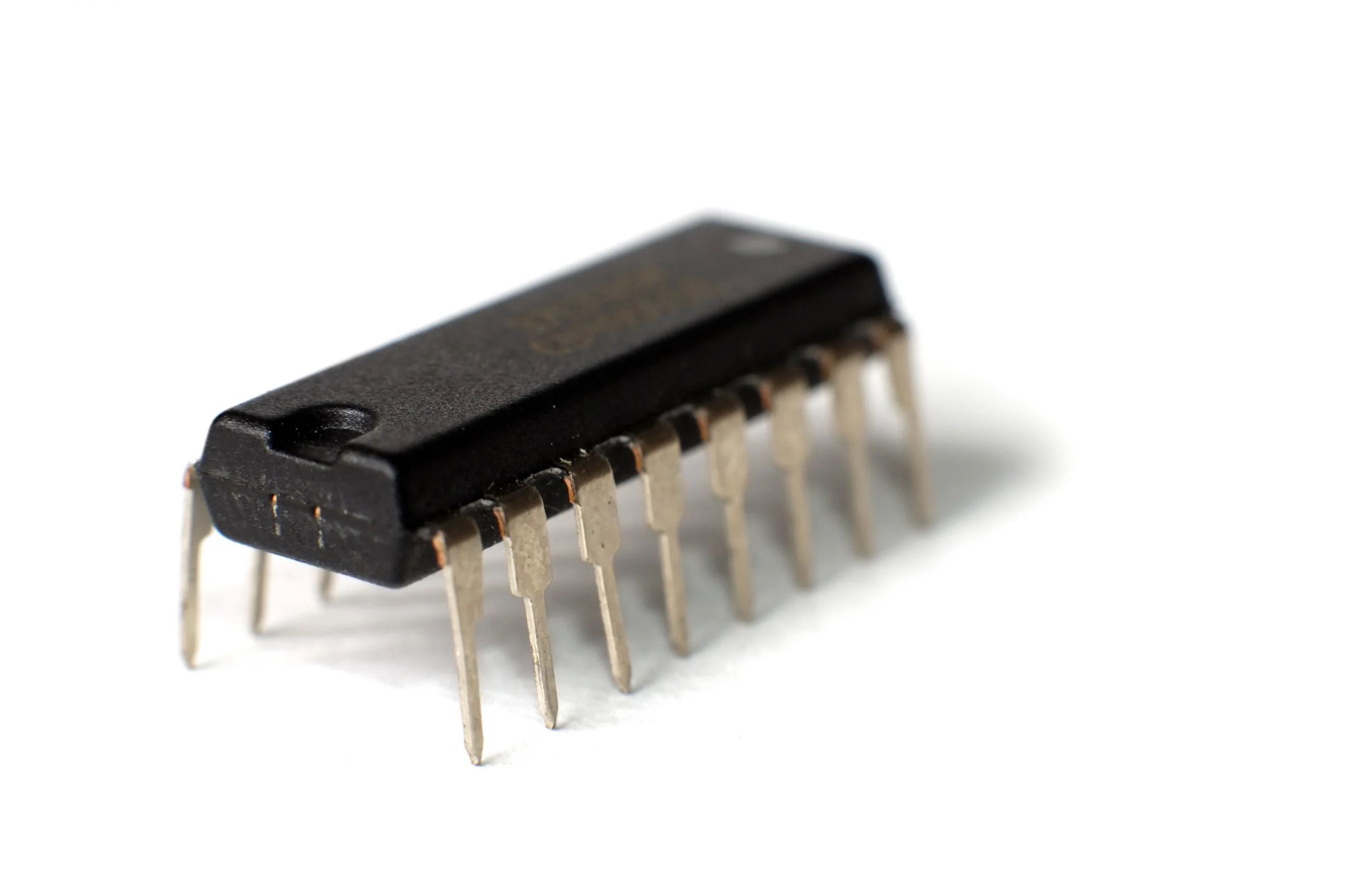
The ULN2803 has 8 open-collector NPN Darlington output channels. Each channel withstands 500 mA current and 50 V output voltage. Thanks to the 2.7 kΩ series resistor per input it is compatible with 5 V TTL/CMOS, for inductive loads the internal suppression diodes are used via the COM pin. When more current is needed, the outputs can be connected in parallel. Its DIP-18 through-hole package allows easy assembly on prototype and series production boards.
You can order this IC from Fark Tedarik with a company invoice:
You can browse other driver and logic ICs in our Integrated Circuits category.
Additional Advantages and Usage Tips
When driving inductive loads, always connect the COM pin to the load supply (for example the 12 V relay supply), otherwise the suppression diodes do not work. Although the limit is 500 mA per channel, the total power dissipation of the IC and the ambient temperature must be taken into account, when several channels run at high current at the same time it may be necessary to reduce the current per channel. Also allow for a saturation voltage of about 1 V or slightly more at the output, depending on the current, because of the Darlington structure.
If you are short of pins, you can use the IC together with a shift register and drive many relays with only 2–3 microcontroller pins. For bulk purchases and project-based needs contact Fark Tedarik: https://farktedarik.com/iletisim/.
Frequently Asked Questions
What is the difference between the ULN2803 and the ULN2003?
The ULN2803 has eight channels and comes in an 18-pin package, the ULN2003 has seven channels and comes in a 16-pin package. The working principle and the current limit per channel are similar.
Can the ULN2803 be used with a 3.3 V microcontroller?
The inputs of the ULN2803 are designed for 5 V TTL/CMOS levels. Although it can work with 3.3 V logic in many applications, it may not switch fully on with high-current loads, in that case the input conditions in the datasheet should be checked.
Can the ULN2803 control the direction of a DC motor?
No. The ULN2803 only switches the load to ground (low-side driver). To change the direction of a DC motor, an H-bridge driver is needed. Unipolar stepper motors, however, can be driven with the ULN2803.
Where should the COM pin be connected?
When driving inductive loads such as relays, solenoids or motors, the COM pin should be connected to the positive terminal of the load supply. This way the internal diodes suppress the reverse voltage.