
Teknik Rehber
What Is a Shift Register? Expanding Microcontroller Outputs with the 74HC164 and CD4094
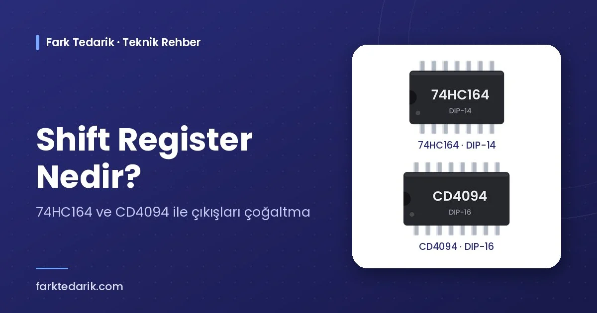
A shift register is a logic IC that stores serial data by shifting it one stage on each clock pulse and transfers it to parallel outputs. Its most common use is controlling 8, 16 or more outputs with only 2–3 pins of a microcontroller. In this article we explain how it works and compare two classic ICs, the 74HC164 and the CD4094, for those looking into “what is a shift register”, “how to use the 74HC164” or “what to do when there are not enough microcontroller pins”.
How a Shift Register Works
A serial-in / parallel-out (SIPO) shift register consists of flip-flops connected in series. On each clock (CLOCK) pulse the bit at the data input is taken into the first flip-flop and the previous bits shift one stage forward. After eight clock pulses the 8-bit data is ready at the 8 parallel outputs of the IC.
There are two different approaches here. In ICs without a storage register, such as the 74HC164, the outputs also change momentarily while data is being shifted. In “shift-and-store” ICs such as the CD4094, the data is first shifted in the internal register and then transferred to the outputs at once with the STROBE signal, so no flicker is seen on the outputs during shifting. Several ICs can be cascaded through the serial output to get 16, 24 or more outputs.
Where Is It Used?
Shift register ICs are a versatile building block in digital electronics:
- Microcontroller Output Expansion: Many LEDs, relays or control signals are driven with few pins.
- Driving LEDs and 7-Segment Indicators: On indicator panels segment and digit data are sent serially.
- Dot Matrix and LED Displays: Row and column data are scanned with a chain of shift registers.
- Serial–Parallel Data Conversion: Parallel control data is carried to a remote board with few wires.
- Control Panels: Used together with relay drivers to build multi-channel output boards.
Why Is a Shift Register Needed?
The number of I/O pins of microcontrollers is limited and more pins usually means a larger and more expensive package. A shift register multiplies the number of outputs almost without limit with a few pins, reduces the tracks on the board and lowers the number of wires. It also separates the outputs from the microcontroller, so in case of a fault a cheaper IC can be replaced. The most common answer to questions like “how to light 16 LEDs with Arduino” is also to use a shift register.
The Solution: 74HC164 and CD4094 Shift Register ICs
The 74HC164 (ST M74HC164) is an 8-bit serial-in / parallel-out shift register from the high-speed CMOS (HC) family. It has two AND-gated serial data inputs (A, B) and an asynchronous, active-low CLEAR input. It works in the 2–6 V supply range and reaches a typical clock frequency of 62 MHz at 6 V. Its DIP-14 package is pin and function compatible with the standard 74HC164.
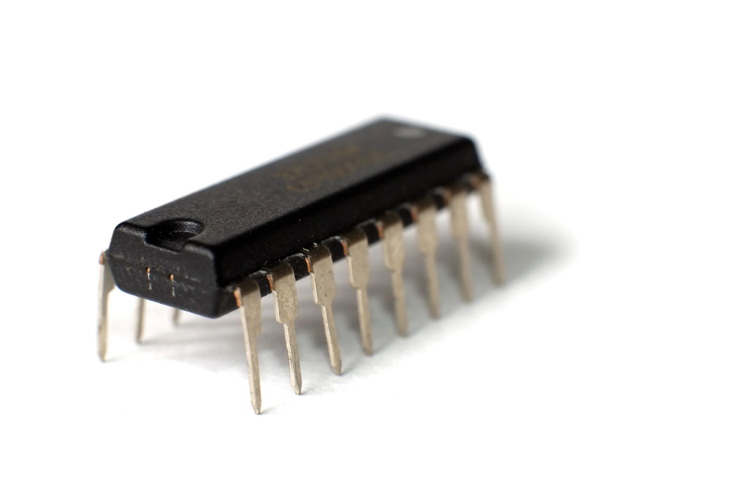
In applications where the outputs must not change during shifting, the CD4094BE stands out. This 8-stage shift-and-store bus register from Texas Instruments’ CD4000 CMOS family offers storage with STROBE, 3-state output control with OUTPUT ENABLE and two serial outputs (QS, Q’S) for cascading. Working over a wide supply range of 3–18 V allows it to be used directly in 12 V control circuits. It comes in a DIP-16 package.
You can order these ICs from Fark Tedarik with a company invoice:
You can browse other logic and driver ICs in our Integrated Circuits category.
Additional Advantages and Usage Tips
Shift register outputs can supply only a few mA, to drive relays, motors or high-current LED arrays you need to add a driver to the outputs. The most widely used solution for this is the ULN2803 Darlington transistor array. When using the 74HC164, remember that the outputs change briefly while data is being sent, although this is too fast for the eye to notice, it may be undesirable with loads such as relays, and the CD4094 should be preferred in such applications.
You can also use shift registers for row and column scanning in dot matrix LED display projects. For bulk purchases and project-based needs contact Fark Tedarik: https://farktedarik.com/iletisim/.
Frequently Asked Questions
What is the difference between the 74HC164 and the 74HC595?
The 74HC164 has no storage (latch) register, the outputs change while data is shifted. The 74HC595 has a separate storage register and 3-state outputs. Similarly, if the outputs must stay steady during shifting, the CD4094 with its storage register can be used.
What is the difference between the 74HC164 and the CD4094?
The 74HC164 belongs to the high-speed HC family, works with 2–6 V and has no storage register. The CD4094 belongs to the CD4000 CMOS family, works with 3–18 V and offers storage with STROBE and 3-state output control with OUTPUT ENABLE.
How are several shift registers connected?
The last output of the first IC (QH on the 74HC164, QS on the CD4094) is connected to the data input of the next IC, and the clock line is shared. This way 16, 24 or more outputs are obtained with the same pins.
Can a relay be driven with a shift register?
It should not be driven directly, the output current is limited. By adding a Darlington driver such as the ULN2803 to the outputs, relays, solenoids and motors can be driven safely.